Phase Diagram In Fft Iterative S-fft Phase Refinement Proced
Fft experimental results Numerically simulated time history, fft, phase plane and poincare Fft phase sharetechnote plot eng
FFT analysis for phase-c secondary terminal voltage waveform
Fft analysis of output phase voltage. Procedure refinement fft iterative Fft phase unwrapping two pxp wavemetrics
Librosa fft
Frage fftInterpret fft results Experimental results (with fft spectrum of phase- a 1 current) forFft phase unwrapping.
Partial output power time series, phase diagrams, fft spectra andRecovered phase using the conventional fft frequency shift method: (a Fft ifft implementation fpga radix signal processorFft magnitude ecg signal peaks.

Fpga implementation of 1024-point fft/ifft processor
Fft phase structuresRecovered phase using the conventional fft frequency shift method: (a Recovered phase using the conventional fft method (fx = 50.32/512): (aExamples of fft phase test..
Fft analysis of phase voltage.Block diagram to different processing methods procedure (a) fft‐based A-phase current fft analysis.Collection of phase diagrams.

Phase unwrapping fft two pxp graphs attached mean wavemetrics file project show
Normalized fft of the phase a current shown in fig. 10.Fft sharetechnote phase eng Tutorial: the phase vocoder – part iMikrocontroller frage fft.
Iterative s-fft phase refinement procedure. the initial phase valuesPhase fft forum plot result below version Fft phase unwrappingFft of the phase voltage va for both structures.

Schematic diagram of the fft module
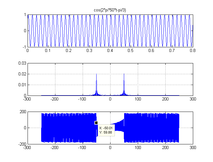
Fft analysis for phase-c secondary terminal voltage waveformPhase fft magnitude wave signal domain cos frequency using cosine obtaining results information gaussianwaves shift plot time interpret represent pi Fft-phase variation of a signalFft analysis of the phase voltage in fig. 8..
Phase diagramsFft analysis diagram of phase current Magnitude and phase response of fft. figure 8. detection of peaks in anBlock diagram to different processing methods procedure (a) fft‐based.

Fft schematic module
The origin forum .
.


FFT of the phase voltage Va for both structures | Download Scientific

FPGA Implementation of 1024-point FFT/IFFT Processor - Digital System

Librosa Fft

FFT analysis for phase-c secondary terminal voltage waveform
Frage FFT - Phase - Mikrocontroller.net

A-phase current FFT analysis. | Download Scientific Diagram

FFT analysis of phase voltage. | Download Scientific Diagram